$99.50
On Hold
OBD Simulator OBD Develop Test Tools ECU Testing Engine Simulator LCD Display
More than 10 available
Details
Shipping: US-Mainland: free (more destinations)
Condition: Brand new
*The store has not been updated recently. You may want to contact the merchant to confirm the availability of the product.


OBD MINI simulator operating instructions
OBD MINI simulator is a simulation of the vehicle OBD bus protocol simulator device. With dynamic simulation engine parameters; LCD display content main parameters in real time.
The following key data characteristics:
1, Supports real-time Data flow Mode1 Live Data
2, Support trouble-free code model, a fault code mode, fault code function Mode3, Mode4
3, Support to Freeze the data Frame Mode2 Freeze Frame
4, Support Vehicle VIN code and other Vehicle Information, Mode9 Vehicle Information
5, Support USB output debugging information, it is recommended to use SecureCRT view
6, The main dynamic parameters of the knob to adjust
7, LCD display the current parameters and state
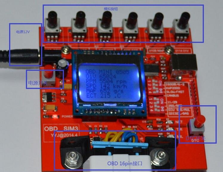
1. Equipment basic instructions:
Below is the equipment physical figure
16 pin OBD interface is a standard interface
Power input to the 12 v dc 2 a
Tthe power switch for the 12 v power supply open close control
Parameters, dynamic update knob can update major OBD several parameters:
010 c RPM on behalf of the Engine speed Engine RPM
010 d VSS on behalf of the Vehicle Speed, Vehicle Speed
0110 MAF represents vehicle air flow sensor of MAF air flow, air flow rate
0105 ECT, on behalf of the Engine coolant temperature Engine coolant temperature
010 b MAP on behalf of the Intake manifold absolute pressure Intake Maniford absolute pressure
0114 O1V representing Bank1 Sensor 1 oxygen Sensor short-term correction
LCD display device simulator at startup parameters such as protocol selection.After the work, according to engine speed, vehicle speed, and MAF air flow parameters.
DTC button control simulator to generate DTC error code
Communication instruction, communication instruction for the three LED indicator light indication, simulator and OBD testing equipment set up after the bus connection, CONNECT light is lit, specific packet communications, T/R indicator lights flashing.
2. The simulator characteristics description:
2.1, support agreement
the ISO 15765 CAN 250 k bit 11 standard protocol
the ISO 15765 CAN 15765 k bit 29 extension protocol
the ISO 15765 CAN 500 k bit 11 standard protocol
the ISO 15765 CAN 15765 k bit 29 extension protocol
the ISO 9141 protocol
the ISO 14230 quick initialization protocol
the ISO 14230 baud five initialization protocol
2.2.Support for fault code, DTC generated definition, freeze frame generated
Key parameters, the RPM speed, VSS speed, fuel consumption, MAF VCT coolant liquid crystal display (LCD), etc
Support sending and receiving data USB log output, including the packet and KWP2000, log USB interface for display in the PC serial port, baud rate to 115200
3. A simple test work instructions
a, OBD work mode setting, all switch to the right, the CAN BUS switch to the left, set up to simulate the vehicle CAN BUS BUS (typical) vehicle.
b, plugged into a power supply, open the power switch,
c, insert the OBD device under test, observation NET light and T/R to send and receive signals.
d, after the OBD two-way communication to establish a connection, a.net indicator, the LCD display shows the Connect.At the same time have a T/R to send and receive.
4. Mode Selection
CAN BUS mode, the fourth CANBUS dial the code switch dial to the right, the rest of the dial to the left, at the same time in the CAN BUS mode, CAN choose 250 KBPS / 500 KBPS two baud rate (dial the code switch) 5, 11 bit standard frame, 29 bit extension frame two frame format (the sixth dial the code switch)
KWP2000 mode, the second KWP2000 dial dial the code switch to the right, the rest of the dial to the left, at the same time in the KWP2000 mode, can choose FAST/missile two initialization mode (the third dial the code switch)
ISO9141 mode, to dial the code switch first ISO9141-2 dial to the right, the rest of the dial to the left
Package:OBD Simulator OBD Develop Test Tools ECU Simulator MINI *1
OBD MINI simulator is a simulation of the vehicle OBD bus protocol simulator device. With dynamic simulation engine parameters; LCD display content main parameters in real time.
The following key data characteristics:
1, Supports real-time Data flow Mode1 Live Data
2, Support trouble-free code model, a fault code mode, fault code function Mode3, Mode4
3, Support to Freeze the data Frame Mode2 Freeze Frame
4, Support Vehicle VIN code and other Vehicle Information, Mode9 Vehicle Information
5, Support USB output debugging information, it is recommended to use SecureCRT view
6, The main dynamic parameters of the knob to adjust
7, LCD display the current parameters and state
1. Equipment basic instructions:
Below is the equipment physical figure
16 pin OBD interface is a standard interface
Power input to the 12 v dc 2 a
Tthe power switch for the 12 v power supply open close control
Parameters, dynamic update knob can update major OBD several parameters:
010 c RPM on behalf of the Engine speed Engine RPM
010 d VSS on behalf of the Vehicle Speed, Vehicle Speed
0110 MAF represents vehicle air flow sensor of MAF air flow, air flow rate
0105 ECT, on behalf of the Engine coolant temperature Engine coolant temperature
010 b MAP on behalf of the Intake manifold absolute pressure Intake Maniford absolute pressure
0114 O1V representing Bank1 Sensor 1 oxygen Sensor short-term correction
LCD display device simulator at startup parameters such as protocol selection.After the work, according to engine speed, vehicle speed, and MAF air flow parameters.
DTC button control simulator to generate DTC error code
Communication instruction, communication instruction for the three LED indicator light indication, simulator and OBD testing equipment set up after the bus connection, CONNECT light is lit, specific packet communications, T/R indicator lights flashing.
2. The simulator characteristics description:
2.1, support agreement
the ISO 15765 CAN 250 k bit 11 standard protocol
the ISO 15765 CAN 15765 k bit 29 extension protocol
the ISO 15765 CAN 500 k bit 11 standard protocol
the ISO 15765 CAN 15765 k bit 29 extension protocol
the ISO 9141 protocol
the ISO 14230 quick initialization protocol
the ISO 14230 baud five initialization protocol
2.2.Support for fault code, DTC generated definition, freeze frame generated
Key parameters, the RPM speed, VSS speed, fuel consumption, MAF VCT coolant liquid crystal display (LCD), etc
Support sending and receiving data USB log output, including the packet and KWP2000, log USB interface for display in the PC serial port, baud rate to 115200
3. A simple test work instructions
a, OBD work mode setting, all switch to the right, the CAN BUS switch to the left, set up to simulate the vehicle CAN BUS BUS (typical) vehicle.
b, plugged into a power supply, open the power switch,
c, insert the OBD device under test, observation NET light and T/R to send and receive signals.
d, after the OBD two-way communication to establish a connection, a.net indicator, the LCD display shows the Connect.At the same time have a T/R to send and receive.
4. Mode Selection
CAN BUS mode, the fourth CANBUS dial the code switch dial to the right, the rest of the dial to the left, at the same time in the CAN BUS mode, CAN choose 250 KBPS / 500 KBPS two baud rate (dial the code switch) 5, 11 bit standard frame, 29 bit extension frame two frame format (the sixth dial the code switch)
KWP2000 mode, the second KWP2000 dial dial the code switch to the right, the rest of the dial to the left, at the same time in the KWP2000 mode, can choose FAST/missile two initialization mode (the third dial the code switch)
ISO9141 mode, to dial the code switch first ISO9141-2 dial to the right, the rest of the dial to the left
Package:OBD Simulator OBD Develop Test Tools ECU Simulator MINI *1


 HK, NT